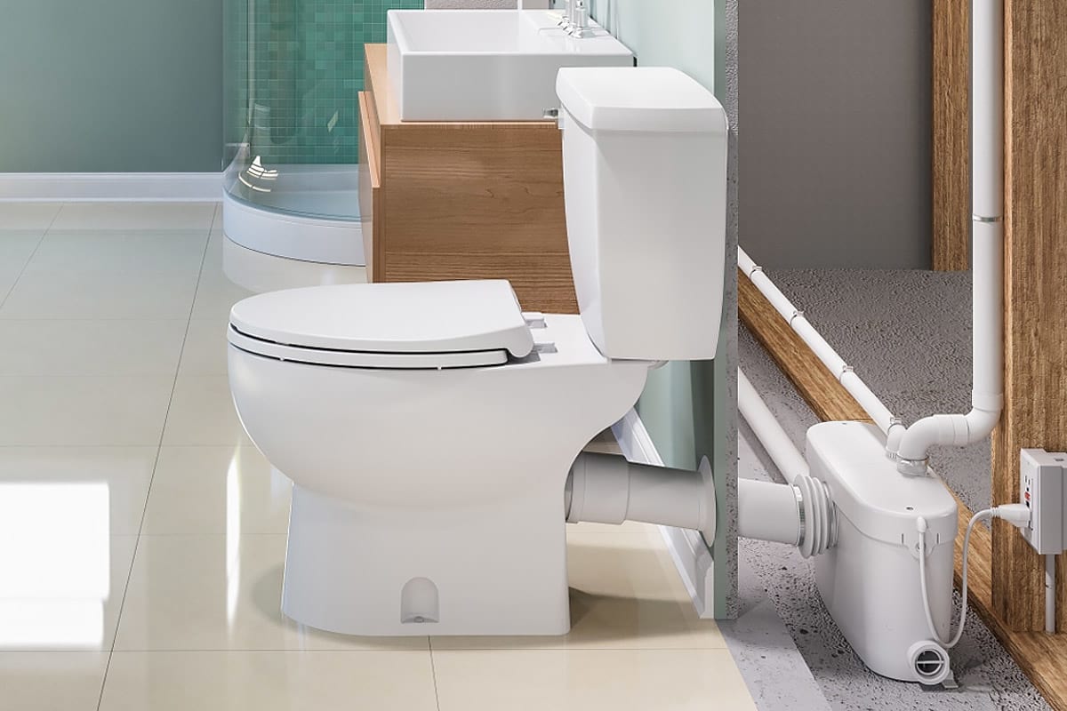
The use of mechanical vents, air admittance valves or similar devices are not permitted as these are considered one-way air vent systems. Please note that the vent system should be a two-way air vent. All plumbing codes require connection to a vent system. This unit has been designed with a vent connection on the lid. A non-return valve (included in assembly) prevents back flow into the unit.
#Saniflo toilet installation diagram pro#
The discharge elbow on top of the Sanigrind Pro can be rotated 360 degrees depending on the discharge installation. The wastewater from other sanitary fixtures is discharged into the Sanigrind Pro via two 2-inch inlets, on either side of the housing. This height difference should be of 8”, to allow for the installation of a P-trap and the required 1/4” per foot gravity flow towards the pump unit. When adding a bathtub/shower, there should be a height difference between the base of the pump and the base of the bathtub or shower.

In addition, the Sanigrind Pro will also discharge gray water from a variety of other sanitary fixtures such as: a sink, a bathtub/shower, a urinal and even a washing machine (indirect connection). The operating cycle for the Sanigrind Pro varies depending upon the discharge pipe run configuration. Once the water level in the container goes down, the micro switch deactivates. The unit pumps the effluent upward to 25 feet and/or 150 feet horizontally (with gravity fall). The reduced solids are picked up at the bottom and the impeller mounted beneath the motor ejects the waste. Water and organic waste matter, enter the chamber and are reduced to slurry as the blades rotate at 3600 RPM. The moving parts therefore are kept to an absolute minimum.

A common spindle/shaft drives the impeller and the blades. The motor is sealed for life in an oil filled enclosure. When the flush is activated, the water flowing into the Sanigrind Pro activates a micro switch in the pressure chamber, which in turn starts the motor. The inside of the Sanigrind Pro comprises of a pressure chamber, which starts and stops the unit, and the motor, which drives the stainless steel cutting blade and the pump. The Sanigrind Pro is designed to handle sanitary products that may have been flushed down the toilet such may consist of condoms, sanitary napkins, q-tips, dental floss, etc. It incorporates a grinder system which is ideal for uncontrolled environments in both residential and commercial applications (ie.
#Saniflo toilet installation diagram install#
The Sanigrind Pro is a 1 HP pump system used to install a complete bathroom up to 25 feet below the sewer line, or even up to 150 feet away from a soil stack.


 0 kommentar(er)
